Message Board

Dear readers, authors and reviewers,you can add a message on this page. We will reply to you as soon as possible!

2019 Volume 41 Issue 9
Article Contents

Rui ZHOU, Yi OU, Bao YU, et al. Research of Geomatric and Radiation Correction of the Hyperspectral Imaging System Carried by a Multi-rotor Unmanned Aerial Vehicle[J]. Journal of Southwest University Natural Science Edition, 2019, 41(9): 141-147. doi: 10.13718/j.cnki.xdzk.2019.09.018
Citation: Rui ZHOU, Yi OU, Bao YU, et al. Research of Geomatric and Radiation Correction of the Hyperspectral Imaging System Carried by a Multi-rotor Unmanned Aerial Vehicle[J]. Journal of Southwest University Natural Science Edition, 2019, 41(9): 141-147. doi: 10.13718/j.cnki.xdzk.2019.09.018

Research of Geomatric and Radiation Correction of the Hyperspectral Imaging System Carried by a Multi-rotor Unmanned Aerial Vehicle

More Information
  • Corresponding author: Yi OU ; 
  • Received Date: 20/08/2018
    Available Online: 20/09/2019
  • MSC: TP7

  • For agriculture, forestry, environmental protection and other industrial applications, the technology of unmanned aerial vehicle (UAV) used in combination with imaging spectrometry has effectively solved the problems of insufficient data and low spatial resolution of hyperspectral remote sensing. But the UAV hyperspectral imaging system is facing a series of other problems, such as expensive equipment, poor data quality and low efficiency. Therefore, it is a key topic of research to develop a low-cost, efficient and convenient UAV hyperspectral imaging system. In this paper, we introduce a hyperspectral imaging system that collects the data of the indoor imaging spectrometer on a multi-rotor UAV. In the study reported herein, control points and standard gray cloths were set up in the test area, and the three-dimensional coordinates of the control points were measured with GPS-RTK and the reflectivity of the standard gray cloths was measured with the ASD feature spectrometer to verify the imaging accuracy of the system. The results of the test was analyzed and evaluated from the aspects of radiation and geometry. In radiation, the reflectivity of the calibrated gray cloth in the hyperspectral data corrected by the radiation calibration and the MODTRAN model was well consistent with that measured by the ASD feature spectrometer. The initial geometric correction of the image with GPS-IMU data and the ground control point coordinates were used to analyze the geometric error after the image processing. The authors recommended that the data accuracy of the geographical positions of the images be improved by correcting the attitude bias angle. In conclusion, this UAV hyperspectral imaging system improves the utilization of indoor imaging spectrometers, and the use of low-precision, low-cost imaging spectrometers and GPS-IMU to collect hyperspectral data is perfectly suited for industry applications.
  • 加载中
  • [1] LI L T, REN T, MA Y, et al. Evaluating Chlorophyll Density in Winter Oilseed Rape (Brassica napus L.) Using Canopy Hyperspectral Red-Edge Parameters[J]. Computers and Electronics in Agriculture, 2016, 126:21-31. doi: 10.1016/j.compag.2016.05.008

    CrossRef Google Scholar

    [2] ENTEZARI I, RIVARD B, LIPSETT M G, et al. Estimation of Methylene Blue Index in Oil Sands Tailings Using Hyperspectral Data[J]. The Canadian Journal of Chemical Engineering, 2017, 95(1):92-99. doi: 10.1002/cjce.22644

    CrossRef Google Scholar

    [3] ZHENG X T, YUAN Y, LU X Q. A Target Detection Method for Hyperspectral Image Based on Mixture Noise Model[J]. Neurocomputing, 2016, 216:331-341. doi: 10.1016/j.neucom.2016.08.015

    CrossRef Google Scholar

    [4] GAO H L, GU X F, YU T, et al. Method Study and Uncertainty Analysis of Calibration Coefficients Validation Based on the Inner Mongolia Test Site[J]. Science China Earth Sciences, 2013, 56(9):1540-1547. doi: 10.1007/s11430-012-4555-4

    CrossRef Google Scholar

    [5] RAFERT J. Advances in Hyperspectral Remote Sensing Ⅰ:The visible Fourier Transform Hyperspectral Imager[J]. Journal of Spectral Imaging, 2015, 4:1-5.

    Google Scholar

    [6] ZARCO-TEJADA P J, CATALINA A, GONZÁLEZ M R, et al. Relationships Between Net Photosynthesis and SteadySstate Chlorophyll Fluorescence Retrieved from Airborne Hyperspectral Imagery[J]. Remote Sensing of Environment, 2013, 136:247-258. doi: 10.1016/j.rse.2013.05.011

    CrossRef Google Scholar

    [7] YU S Q, JIA S, XU C Y. Convolutional Neural Networks for Hyperspectral Image Classification[J]. Neurocomputing, 2017, 219:88-98. doi: 10.1016/j.neucom.2016.09.010

    CrossRef Google Scholar

    [8] MA X R, GENG J, WANG H Y. Hyperspectral Image Classification Via Contextual Deep Learning[J]. EURASIP Journal on Image and Video Processing, 2015(1):1-12.

    Google Scholar

    [9] ZARCO-TEJADA P J, GONZÁLEZ-DUGO V, BERNI J A J. Fluorescence, Temperature and Narrow-Band Indices Acquired from a UAV Platform for Water Stress Detection Using a Micro-Hyperspectral Imager and a Thermal Camera[J]. Remote Sensing of Environment, 2012, 117:322-337. doi: 10.1016/j.rse.2011.10.007

    CrossRef Google Scholar

    [10] DATT B, MCVICAR T R, VAN NIEL T G, et al. Preprocessing EO-1 Hyperion Hyperspectral Data to Support the Application of Agricultural Indexes[J]. Geoscience & Remote Sensing IEEE Transactions on, 2003, 41(6):1246-1259.

    Google Scholar

    [11] GREEN R O, EASTWOOD M L, SARTURE C M, et al. Imagine Speuroscopy and the Airborne Visible/Infrared Imaging Spectrometer(AVIRIS)[J]. Remote Sensing of Environment, 1998, 65:227-248. doi: 10.1016/S0034-4257(98)00064-9

    CrossRef Google Scholar

    [12] COCKS T, JENSSEN R, STEWART A, et al. The HYMAP Airborne Hyperspectral Sensor: The System, Calibration, and Performance[C]//Proceedings of the 1st EARSEL Workshop on Imaging Spectroscopy. Switzerland: Zurich, 1998: 37-42.

    Google Scholar

    [13] ZABCIC N, RIVARD B, ONG C, et al. Using Airborne Hyperspectral Data to Characterize the Surface pH and Mineralogy of Pyrite Mine Tailings[J]. International Journal of Applied Earth Observations & Geoinformation, 2014, 32(1):152-162.

    Google Scholar

    [14] ACEVO-HERRERA R, AGUASCA A, BOSCH-LLUIS X, et al. Design and First Results of an UAV-Borne L-Band Radiometer for Multiple Monitoring Purposes[J]. Remote Sensing, 2010, 2:1662-1679. doi: 10.3390/rs2071662

    CrossRef Google Scholar

    [15] RANGO A, HAVSTAD K, ESTELL R. The Utilization of Historical Data and Geospatial Technology Advances at the Jornada Experimental Range to Support Western America Ranching Culture[J]. Remote Sensing, 2011(3):2089-2109.

    Google Scholar

    [16] REMONDINO F, BARAZZETTI L, NEX F, et al. UAV Photogrammetry for Mapping and 3D Modeling——Current Status and Future Perspectens[J]. Remote Sensing and Spatial Information Sciences, 2011, 22:1-7.

    Google Scholar

    [17] CHIABRANDO F, NEX F, PIATTI D. UAV and RPV Systems for Photogrammetric Surveys in Archaelogical Areas:Two Tests in the Piedmont Region (Italy)[J]. Journal of Archaeological Science, 2011, 38:697-710. doi: 10.1016/j.jas.2010.10.022

    CrossRef Google Scholar

    [18] NIETHAMMER U, JAMES M R, ROTHMUND S. UAV-Based Remote Sensing of the Super-Sauze landslide:Evaluation and Results[J]. Engineering Geology, 2012, 128:2-11. doi: 10.1016/j.enggeo.2011.03.012

    CrossRef Google Scholar

    [19] STACY N J S, CRAIG D W, STAROMLYNAKA J. The Global Hawk UAV Australian Deploynent:Imaging Radar Sensor Modifications and Employment for Maritime Surveillance[J]. In Proc ICARSS, 2002(2):699-701.

    Google Scholar

    [20] BIESEMANA J, EVERAERTS J, LEWYCKYJ N. PEGASUS: Remote Sensing from a Hale-Uav[C]//ASPRS 2005 An-nual Conference. Moryland: Baltimore, 2005: 1-4.

    Google Scholar

    [21] WATTS A C, AMBROSIA V G, HINKLEY E A. Unmanned Aircraft Systems in Remote Sensing and Scientific Research:Classification and Considerations of Use[J]. Remote Sensing, 2012, 4(6):1671-1692. doi: 10.3390/rs4061671

    CrossRef Google Scholar

    [22] ZARCO-TEJADA P J, GONZALEZ-DUGO V, BERNI J A J. Fluorescence, Temperature and Narrow-Band Indices Acquired from a UAV Platform for Water Stress Using a Micro-Hyperspectral Images and a Thermal Camera[J]. Remote Sensing of Environment, 2012, 117:322-337. doi: 10.1016/j.rse.2011.10.007

    CrossRef Google Scholar

  • 加载中
通讯作者: 陈斌, bchen63@163.com
  • 1. 

    沈阳化工大学材料科学与工程学院 沈阳 110142

  1. 本站搜索
  2. 百度学术搜索
  3. 万方数据库搜索
  4. CNKI搜索

Figures(7)  /  Tables(3)

Article Metrics

Article views(2933) PDF downloads(1629) Cited by(0)

Access History

Other Articles By Authors

Research of Geomatric and Radiation Correction of the Hyperspectral Imaging System Carried by a Multi-rotor Unmanned Aerial Vehicle

    Corresponding author: Yi OU ; 

Abstract: For agriculture, forestry, environmental protection and other industrial applications, the technology of unmanned aerial vehicle (UAV) used in combination with imaging spectrometry has effectively solved the problems of insufficient data and low spatial resolution of hyperspectral remote sensing. But the UAV hyperspectral imaging system is facing a series of other problems, such as expensive equipment, poor data quality and low efficiency. Therefore, it is a key topic of research to develop a low-cost, efficient and convenient UAV hyperspectral imaging system. In this paper, we introduce a hyperspectral imaging system that collects the data of the indoor imaging spectrometer on a multi-rotor UAV. In the study reported herein, control points and standard gray cloths were set up in the test area, and the three-dimensional coordinates of the control points were measured with GPS-RTK and the reflectivity of the standard gray cloths was measured with the ASD feature spectrometer to verify the imaging accuracy of the system. The results of the test was analyzed and evaluated from the aspects of radiation and geometry. In radiation, the reflectivity of the calibrated gray cloth in the hyperspectral data corrected by the radiation calibration and the MODTRAN model was well consistent with that measured by the ASD feature spectrometer. The initial geometric correction of the image with GPS-IMU data and the ground control point coordinates were used to analyze the geometric error after the image processing. The authors recommended that the data accuracy of the geographical positions of the images be improved by correcting the attitude bias angle. In conclusion, this UAV hyperspectral imaging system improves the utilization of indoor imaging spectrometers, and the use of low-precision, low-cost imaging spectrometers and GPS-IMU to collect hyperspectral data is perfectly suited for industry applications.

  • 高光谱遥感技术广泛应用于农林、生态环境等[1-3]方面,如作物监测、产量预测[4-5]和环境监测,并根据特征波段反演植被冠层的含水量、叶绿素和氮等物理参数[6].目前,高光谱遥感一般是将传感器安装在载人飞行器上或有限的航天平台上.相比星载高光谱成像系统的质量和精度而言,机载高光谱影像具有很高的空间和光谱分辨率等优势,而且相较于星载而言具有灵活、运营成本低等特点[7-10].但是,针对高性能的高光谱成像系统,如AVIRIS和HyMap[11-12]机载可见光-近红外高光谱成像仪,此类均是搭载在载人飞行器上,而且载人飞行器很长时间才能安排调度,且成本费用较高,容易受天气干扰.此外,载人平台的提供商的时间调度困难.随着轻小型无人机(unmanned aerial vehicle,UAV)技术的发展,基于UAV的高光谱成像系统可以克服飞行器调度和飞行空域限制等难题[13].那么就可以采用新的方式,使用按需定制的平台,在数小时内快速地完成高光谱数据[15-16]的采集工作.

    近年来,UAV飞行技术在军事、摄影测量和倾斜摄影等方面应用较为成熟.到目前为止,相关研究领域已经将UAV、旋翼或固定翼无人机平台与视频、多频带数字相机、量测相机、合成孔径雷达(synthetic aperture radar,SAR)和激光扫描等中的某一种或多种配合使用[17-20].同时,也有很多无人机载高光谱成像系统的研究,主要有框幅式和推扫式,然而,很少有研究成功测试了轻小型、旋翼或固定翼无人机上搭载推扫式高光谱传感器[21-22].而且,现在很多科研院所购置的成像光谱仪仅用于地面高光谱的研究,失去了高光谱遥感本质上的意义.因此,本研究提出了一种地面成像光谱仪、车载全球定位系统(global positioning system,GPS)和惯性测量单元(inertial measurement unit,IMU)与多旋翼无人机集成的低成本线阵推扫式高光谱遥感成像系统.因高光谱遥感成像系统需要经过辐射和几何校正才能进行定量的科学分析,本研究通过实验测试并评价分析此无人机载高光谱成像系统所采集高光谱图像的辐射校准和几何校正的精度.

1.   系统设计
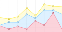
  • 系统设计以UAV为中心,根据UAV载荷重量选择合适的成像光谱仪,原则上选择尺寸紧凑,成本和重量相对低的成像设备.本研究选择美国Resonon的PIKA L可见光-近红外推扫式成像光谱仪(图 1),光谱范围是400~1 000 nm,最小光谱分辨率为2.1 nm,光谱分辨率可根据需求而更改,成像仪裸质量为0.45 kg,尺寸大小为10.0 cm×12.5 cm×5.3 cm.该系统通过机载微型电脑控制数据的采集和存储.

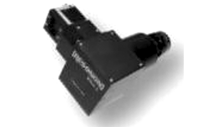
  • 用于本研究的搭载平台为八旋翼电动UAV,该机型载荷可达10 kg,抗风性能强,续航时间可达30~40 min,完全可以满足小范围的农田和环境等监测. UAV自带自动导航驾驶系统,具有独立的GPS-IMU惯性导航定位系统,与获取图像数据中的位置和姿态信息的GPS-IMU互不干扰.多旋翼UVA的PIKA L高光谱成像系统见图 2.

    为了快速有效地对原始高光谱图像进行地理配准,机载GPS-IMU必须满足一下条件:

    (1) 必须确定GPS,IMU和传感器之间的相对位置和方向;

    (2) 飞行期间GPS,IMU和传感器之间的相对位置和方向必须保持不变;

    (3) GPS,IMU和传感器之间必须满足足够精度的时钟同步.

    为了实现这一点,系统设计中采用了大疆生产的RONIN三轴自稳云台,可有效地消除飞机振动产生的位置和方向上的测量误差(表 1).惯导系统、成像光谱仪、微型电脑和云台组合挂载于无人机底部,总质量不超过5 kg.

2.   实验方法
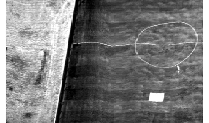
  • 本研究实验数据于2017年4月26日在河北廊坊无人机飞行测试基地采集,该测试区地势平坦,测试区域有人工足球场和农田旱地,裸土植被均有覆盖,具有较强的几何特性和地物特征,并且在飞行区域铺设反射率为35%的人工反射校正参考布.为了评价图像预处理的几何位置精度,在地面均匀布设了113个地面控制点,喷涂红漆加以标识,采用南方S86型GPS-RTK测量准确的地面控制点的三维坐标.数据采集时间在北京时间13:00-15:00之间,此时,天气晴朗无云,光照稳定,有利于成像光谱仪成像.飞行结束后,立即用ASD(analytica Spectra Devices)公司的FieldSpec-4地物波谱仪测量校正灰布的不同部位共30组反射光谱,取平均值作为校正灰布的标准反射光谱.本次实验飞行2个航次,共获取6幅高光谱立方体,以第一幅高光谱影像为例(图 3).

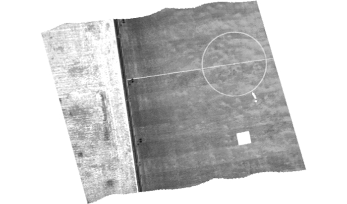
  • 首先,根据仪器制造商提供的辐射定标文件对高光谱图像进行辐射定标,将原始图像DN值转化为辐射亮度数据,并扣除仪器本身自带的噪声.然后,将辐射亮度数据经过大气校正转换成地面光谱反射率,本研究采用MODTRAN辐射传输模型反演地物反射率图像.最后,结合GPS-IMU的坐标和姿态数据进行几何校正(图 4).

3.   评价分析
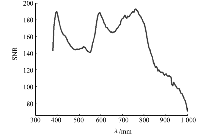
  • 信噪比(signal to noise ratio,SNR)是高光谱成像仪通常要求的参数.本研究评价描述了高光谱图像SNR的计算,可以计算其良好的近似为

    其中:Φ(λ)为高光谱成像仪收集的信号,单位为焦耳;h是普朗克常数;c是光速;B是采集信号时进行合并操作数目;iDark为暗电流噪声,单位为“个电子/s”;eRead是电子中的读取噪声;Δt是以秒为单位的积分时间.

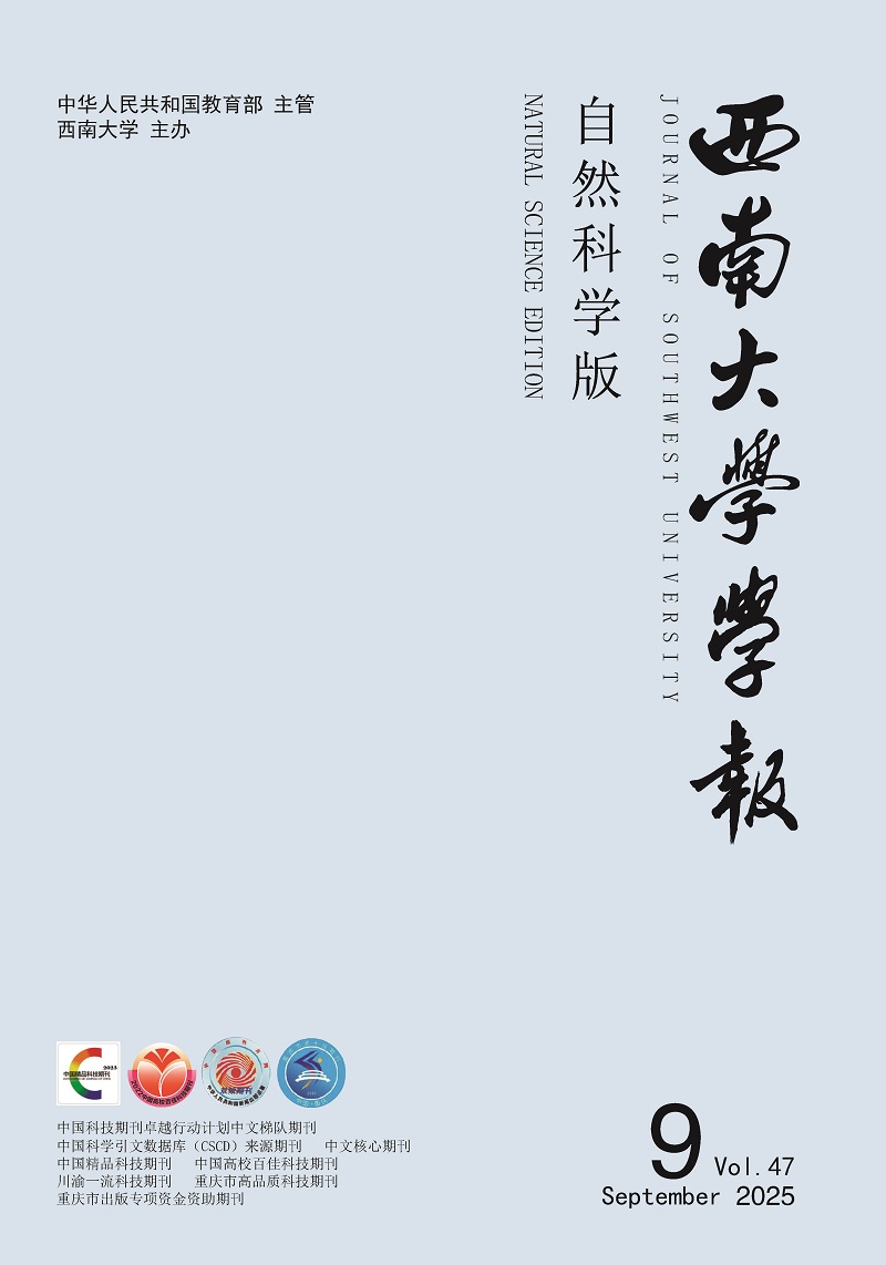
    采用(1)式计算147个波段的信噪比(图 5).从图 5可以看出,UAV高光谱影像的信噪比在波段首尾位置较低,而且不同波段的信噪比均存在一定的差异,信噪比与反射率成正相关,反射率高的波段SNR相对会高一些.波段首尾位置信噪比低的原因是成像光谱仪在紫光附近和近红外附近受到噪声干扰明显导致,在紫光附近的反射率较低,近红外的成像信号没有可见光部分稳定,且近红外波段受噪声干扰更为明显.因此可以通过对图像降噪的方法提高信噪比,进而也平滑了反射率光谱曲线.

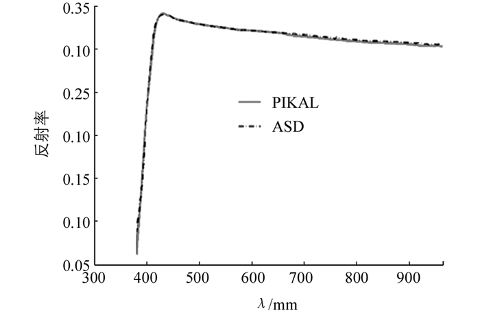
  • 在高光谱遥感图像辐射分析中,除了计算图像的信噪比,最为关注的是光谱曲线的能否准确反映地物的真实情况.研究中购置的标准参考布的反射率在35%左右,并在同一时间用ASD地物光谱仪测量不同部位的反射率的平均值作为标准参考.实验将ASD地物光谱仪测量的标准参考布反射率与高光谱图像中标准参考布进行对比(图 6),以验证UAV成像系统采集的光谱数据的准确性.

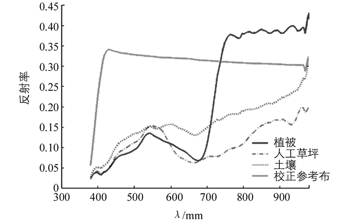
    为了进一步分析UAV机载成像系统的性能,从高光谱影像中提取几种典型地物的光谱曲线,主要有植被、人工草坪、土壤和校正参考布,改4种地物光谱曲线如图 7所示.从图 7可以看出,4种地物在UAV成像系统中获取的光谱曲线在可见光-近红外部分最为平滑,受干扰最小,能够准确地反映相应的地物光谱信息,从而也证明UAV高光谱成像系统获取数据稳定可靠.

  • 高光谱图像经过GPS-IMU采集的坐标和姿态信息进行地理配准和几何校正之后,因GPS-IMU测量存在一定的误差,图像上地理位置仍然会有误差存在.因为GPS-RTK的测量误差只有几个厘米,而机载GPS属于单点定位模式,GPS-RTK的测量精度远远高于机载GPS的精度,故用地面GPS-RTK测量的坐标值作为控制点准确值,计算在图像中找到有红色标识的拐角点和人工标记的地面控制点,获取影像上有地面测量数据相应标识点的坐标信息,并与GPS-RTK测量的坐标进行比较.在评价图像几何形变时,通常只考虑平面上的畸变程度,从而本研究计算WGS-84坐标系下ΔxΔy的值以评价机载高光谱图像的几何精度.统计6幅UAV高光谱影像的几何精度见表 2.

    高光谱图像经过几何校正后,图像中地物的形状与实际相同,但是,若需要满足测绘制图的精度还是远远不够.本着低成本高效率的宗旨,所选择的机载GPS-IMU为单点定位模式,定位精度有限,价格最便宜,但是已经足够满足高光谱遥感在农林生态行业的应用.若需要提交图像的几何地理位置精度,可以从以下两个方面提高:一方面可以从设备上改进,采用RTK测量定位采集坐标信息和使用高精度的惯导系统,但这又增加了UAV集成的成本;另一方面,根据地面控制点计算图像存在的偏差,反算传感器的姿态偏移角度误差,并通过平差减小误差,重新对图像进行几何校正.因而,本研究采用第2种方法提高位置精度,表 3为调整姿态偏移角度后计算图像的几何误差.从表 2表 3对比分析,可以看出不管是经纬度还是总的位置误差都有明显的提高.而且,针对第一种情况,也做过相应实验,位置精度能达到厘米级.

4.   结论
  • 本研究从充分利用室内成像光谱仪、节约成本和轻便地获取高光谱遥感影像数据等角度考虑,基于机载POS的航测原理,将价格便宜的GPS-IMU和小型的成像光谱仪紧凑地集成于多旋翼无人机上采集合格高光谱数据.研究通过增加三轴自稳云台以减小UAV自身机械振动所产生的测量误差,从而能获取更准确的姿态、位置和光谱信息.利用测量的辅助数据对高光谱图像进行辐射定标、大气校正和几何校正等预处理工作,并从辐射和几何两个方面分析评价UAV高光谱成像系统的可靠性.实验结果表明,组合GPS-IMU和高光谱成像设备通过三轴自稳云台挂载于多旋翼UAV上采集的高光谱影像数据可靠,系统操作灵活便捷;而且,辐射和几何精度均可满足研究和应用的需求,达到了节约成本和现有设备综合利用的目的.

Figure (7)  Table (3) Reference (22)

Catalog

    /

    DownLoad:  Full-Size Img  PowerPoint
    Return
    Return